1 (edited by iitzex 2024-04-02 04:31:53)

Topic: Could I make my own power supply

I got my adi-2 burn, and saddly it was an old one.
It means no Guarantee, so I try to fix by myself.

I found the V-test plug-in, could I have the voltage mapping to supply the machine?
As far as I know, 1.2V, 1.8V, 3.3V, 5VA, 16V, -16V, 15V, -15V.
Since it was screwed, I would try to use linear power.

Any help?
thx

2 (edited by KaiS 2024-04-01 18:42:51)

Re: Could I make my own power supply

Why not just fix the internal power supply?

If you‘re capable to built a new multi-voltage linear PSU, you should be able to find the faulty electronic part and replace it.
Trace the DC voltage and see where it‘s lost, this is about where the fault sits.

If you‘re out for help you should mention the exact model of ADI-2, there are 4 different models and several versions of each.


BTW:
I don‘t know and can’t find a “V-Test Plugin” but a cheapo $20 multimeter is the only tool needed for this kind of fault-finding.

3 (edited by iitzex 2024-04-02 05:43:00)

Re: Could I make my own power supply

KaiS wrote:

Why not just fix the internal power supply?

If you‘re capable to built a new multi-voltage linear PSU, you should be able to find the faulty electronic part and replace it.
Trace the DC voltage and see where it‘s lost, this is about where the fault sits.

If you‘re out for help you should mention the exact model of ADI-2, there are 4 different models and several versions of each.


BTW:
I don‘t know and can’t find a “V-Test Plugin” but a cheapo $20 multimeter is the only tool needed for this kind of fault-finding.

My own adi-2 is ak4490, version 3V2.
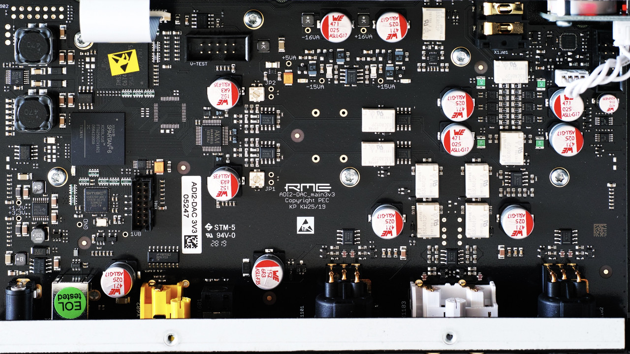
I'll use the picture from internet to explain, thx.

https://i.postimg.cc/CKP3WV1p/V3.jpg

Without schematic, it's hard to figure out for my poor ability.

I burn the tvs diode, and it got dead to short the Vin and Gnd.
So I replace it, but it still got no 3.3v.
I'm not sure anything else burn?
tps54294(left and bottom corner) should convert Vin to 3.3v,
when I push the red button, pin 12(en2) got 3.3v, but still no 3.3v from pin14(sw2)
According the datasheet, it used10v to enable, I'm not sure what's wrong, or is 3.3v enough to enable the DCDC converter?
pin 5(en1) seems to connect to 3.3v, so no voltage out from pin3(sw1).

And tps55340(left and up corner) may convert Vin to +16V, -16V.
But I don't know how to enable it.

The V-test pulg-in just near by TI's DSP.

It seems easier to using power from outside, with schematic.
For me, it's really hard to trace.
Or could someone help, please send me schematic in P.M.

Thx for the help and bother.

Re: Could I make my own power supply

Variations of the PSU input circuit exist.

The diode works as a shunt for the reverse voltage protection.
There are other parts involved in this, some versions have a PTC, some have a tiny fuse.

Trace the external 12 V DC to the DC-DC converter chips.
Do they “see” 12 V?

Else there’s still a broken part in this path.


BTW: the schematic is confidential, I don’t have it.

5

Re: Could I make my own power supply

PCB v3.2 has polarity protection after the input voltage limiting diode. Therefore I expect there has been more than 20 V at the DC input (wrong power supply), and chips like the TPS54294 (max input voltage 20 V) hanging on the +12 V bus have also been damaged. It also seems unrealistic to feed all the needed voltages externally. These are partly very special regulators, plus the timing how they ramp up is important, plus they need to be super low noise, plus they need a perfect Ground connection with the rest...

Regards
Matthias Carstens
RME

Re: Could I make my own power supply

MC wrote:

PCB v3.2 has polarity protection after the input voltage limiting diode. Therefore I expect there has been more than 20 V at the DC input (wrong power supply), and chips like the TPS54294 (max input voltage 20 V) hanging on the +12 V bus have also been damaged. It also seems unrealistic to feed all the needed voltages externally. These are partly very special regulators, plus the timing how they ramp up is important, plus they need to be super low noise, plus they need a perfect Ground connection with the rest...

After replace tvs diode, Vin(12v) did exist.
And, I already tried to replace the tps52294, but still the same, no 3.3V.

Anyway, thx.
I'm still struggle with the power rails, and hope something good news will happen.

Re: Could I make my own power supply

I wonder if there are any repair services for the ADI-2 DAC after the warranty has expired. So you can send your device, get a quote, get it repaired and they will ship it back to you.