
Topic: New SteadyClock FS in ADI-2 Pro (249) and DAC (35)
In this post
https://forum.rme-audio.de/viewtopic.ph … 12#p167412
I briefly wrote about the latest changes with SteadyCock FS, which I later explained in more detail in the firmware update thread here:
https://forum.rme-audio.de/viewtopic.php?id=32772
I promised to show the difference in behaviour with measurements on my APx555B, but did not find the time so far. Forum user KSTR performed some measurements to confirm that SteadyClock indeed works as good as we claim in three posts found on ASR:
https://www.audiosciencereview.com/foru … ost-727138
Time for some measurements to be shown in our own forum!
The first measurement shows the influence of jitter on the THD+N value of an ADI-2 DAC which is fed by a jittered SPDIF signal. Jitter modulation is a low 50 Hz, and the amount of jitter (x-axis) rises from 10 ns up to 500 ns (remember anything above 100 ns is unreal and will already cause loss of sync with many devices. Even 50 ns is very unlikely to ever occur in real-world scenarios).
The y-axis shows the measured THD+N, distortion and noise. The test signal for this part is a simple 1 kHz sine at 0 dBFS, transmitted via optical cable with a constantly rising amount of jitter.
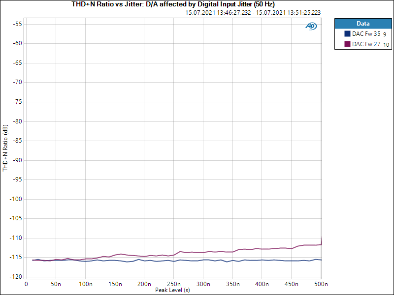
Two curves are shown. The blue line shows the latest SteadyClock with firmware 35, which incorporates a jitter filter at around 1 Hz. The line proves that, as the 50 Hz jitter modulation does not affect the measured THD+N even at an enormous 500 ns of jitter. In firmware 27, the red line, rising jitter cause the THD+N to degrade a bit, starting at around 100 ns of jitter. We claimed that SteadyClock efficiently removes jitter from around 200 Hz up, but as one can see here it also works at 50 Hz, just not that much as with higher modulation rates.
The difference becomes more clear in the next measurement. This one is the ADI-2 Pro in Digital Thru mode, AES in to AES Out. This setup allows to directly measure the jitter influence on the clock, without the added jitter suppression of the DAC chip (both ADC and DAC perform some jitter reduction too, but no chip manufacturer publishes numbers of that behaviour). The AES signal includes a simple 1 kHz sine, although it does not change the result at all when no audio is sent (digital 0).
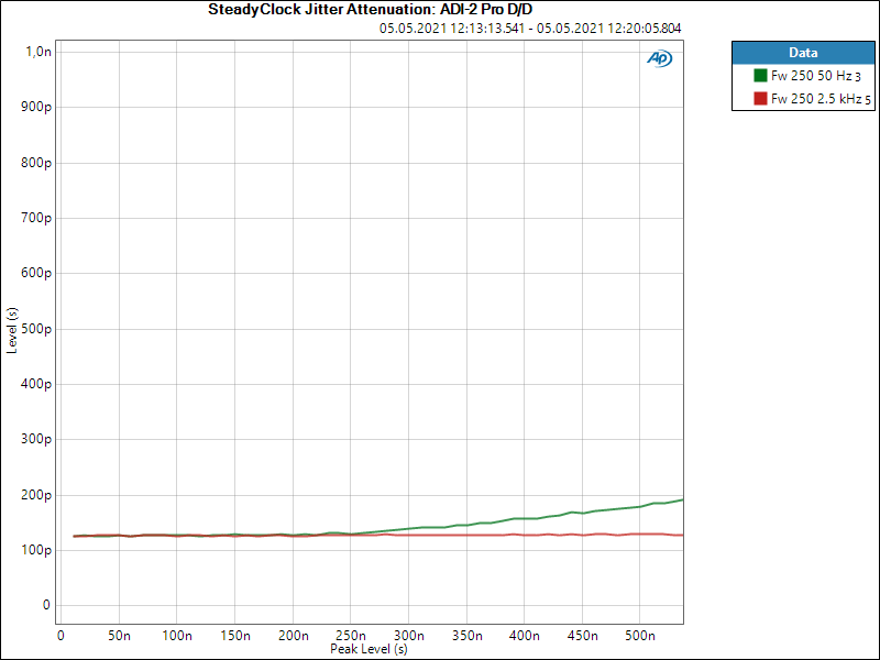
This measurement shows that with the new firmware 250 jitter modulation of 50 Hz at up to around 250 ns has no measurable effect. Above 250 ns the jitter ‘bleeds through’, but the amount is so low that it doesn’t affect performance at all, as the next measurements will show.
In the next measurement the AES signal is modulated with fixed 0 ns, 100 ns and 400 ns of jitter. The frequency of the modulation is swept from 20 Hz up to 20 kHz. Four measurements are shown. Green and red show that 0 and 100 ns of jitter even down at 20 Hz are more or less identical or unaffected. At 400 ns finally the blue line shows that some jitter comes through. 400 ns here turns into 210 ps, which represents a jitter attenuation of 65.6 dB.Very nice!
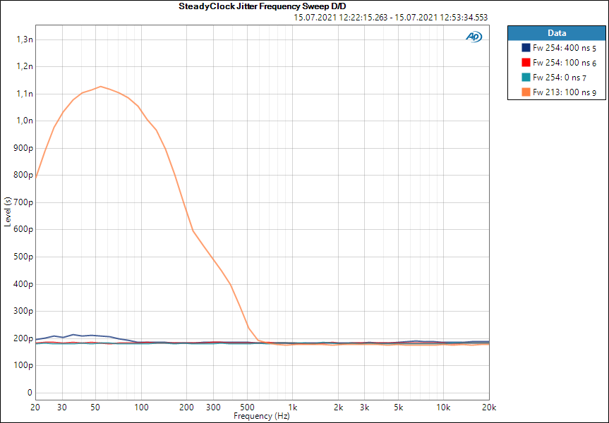
The orange curve is the former firmware 213. Here 100 ns is reduced to 1.12 ns, attenuated by 39 dB. Nice as well!
The APx555B can directly use FFT analysis on the carrier (the digital input signal itself), which gives a better view into the jitter attenuation of the modulation frequency. Here the modulation is intentionally set to 10 Hz, so only a bit above the 1 Hz corner frequency of our updated SteadyClock. The turquoise curve is the former firmware 213 with 400 ns of 10 Hz jitter. Around 2 ns are left of it. Firmware 254 shows around 18 ps. To showcase the improvement in a different way I set the amount of jitter so that old and new firmware match. The 400 ns of the new firmware give the same amount of jitter as 8 ns of the old firmware (blue and orange curve at 10 Hz).
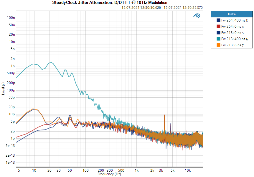
Unfortunately trying to measure jitter below 50 Hz is unspecified with the APx, so there are various effects occuring that forbid to document exact jitter values. But the FFT can still be used to demonstrate that the new SteadyClock filters incoming low frequency jitter much better than the already good former one.
Long time users know that we always try to further improve our designs. We have some ideas to make SteadyClock even better, by firmware update. If that happens you will read about it here.
Matthias Carstens
RME