1 (edited by axell 2011-02-03 23:27:55)

Topic: Hdsp 9632 - DIY Analog Breakout Cables -

Hi,
I am using my RME HDSP 9632 for playback only and I'm trying to "clean up" a bit the cable mess and the noise from my system. All I want is just to make a good quality cable long enough from my RME card to my amp so i do not have to use a second cable any more. Would it be please possible to get the schematics / pictures / diagrams of the pinout assignment for both unbalanced and balanced breakout cables? According to the manual, on the unbalanced version, the pins 1, 9, 11 are labelled as GND/Shell. My question is: Are all these pins acting as one GND connection for both L & R channels or there is a recommended configuration? Also is the metal casing of the D-Sub connector connected somehow to GND as well (is this the Shell?)? Thank you in advance.
Best Regards,
Axell
2

Re: Hdsp 9632 - DIY Analog Breakout Cables -

The pinouts are in the manual, correct. The main ground connection for phones is pin 9, with everything else connected to the shell for a separate ground connection.

Regards
Matthias Carstens
RME

Re: Hdsp 9632 - DIY Analog Breakout Cables -

Hi MC,
I do appreciate your quick reply but would you please elaborate. I am not using and I do not intend to use phones so... I am a bit confused here ... According to the manual (unbalanced version): Pin 3 = Line Out Right +  and  Pin 12 = Line Out Left +. All I want to find out is on which pins I have to solder the GND(-) of the Left & Right RCA connectors. That's it. Sorry if I missed something in your explanation.
Best Regards,
Axell

4

Re: Hdsp 9632 - DIY Analog Breakout Cables -

Shell only or pin 9 plus shell...wahtever you prefer.

Regards
Matthias Carstens
RME

Re: Hdsp 9632 - DIY Analog Breakout Cables -

Much better; thanks very much. I'll let you know how it's going (sounding).
Best Regards,
Axell

6 (edited by axell 2011-02-28 23:46:45)

Re: Hdsp 9632 - DIY Analog Breakout Cables -

Hi,
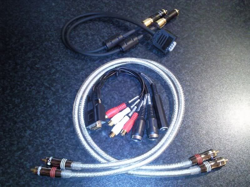
Didn't have too much time the past weekends, but here I have it done now. About the sound - nothing extraordinary yet, slightly bass improvement and less noise/interferences which IMO is not too bad for a 1st try. As the next step I was thinking to re-do the job but with a better cable.
Best Regards, 
Axell

http://i135.photobucket.com/albums/q147/dnldnt/album2006/RME/RMECABLE003.jpg

Photo1:
http://s135.photobucket.com/albums/q147 … BLE001.jpg

Photo2:
http://s135.photobucket.com/albums/q147 … BLE002.jpg

Photo3:
http://s135.photobucket.com/albums/q147 … BLE003.jpg

Re: Hdsp 9632 - DIY Analog Breakout Cables -

Ok here's one.

I'm handy with soldering analog balanced cable a db15 connectors.
However, the only male vga connector I had on hand has pin 9 missing.

So on the schematic at the end of the pdf manual for the 9632 it shows pin 9 as GND/SHELL. So I thought, "Pfft, what could go wrong" and soldered the cable shields together then soldered that shield group to the shell.

Well one input side is waaay down in level and muffled so, is this a proper way do wire this?
I have buzzed out the cable a couple of times and it all looks cool. Maybe one side on the card is dead at the input.


TIA

:Ron