1 (edited by Happy_amateur 2024-10-01 16:11:19)

Topic: Wiring from D-sub contact

Ive been working on small stereobench for my 9.5" RME boxes ADI-2 PRO and UCX2.  For this I have made a row of eight AES and Spdif contacts to reside at the back of the bench. This is supposed to connect with DB-9 to DB-9 cable from electronics to the bench I/O

https://imgur.com/a/WLna55k

A couple of questions have come to mind though. Wiring in manual is self-explanatory, but I seem to have messed up my mind about it

1. AES ground puzzles me. Is it common for in and out, or is it just connected to one of the contacts? On the AES contact there is also a solder point for chassi-ground. Can someone make sense for me.

2. Importance of internal cabling. I have some nice thin 110ohm installation cable and 75ohm coax I ripped from a video cable to use. WC cable reflections has become a mind-bug for me, but now I want to ask the forum; Is this a real problem with a stretch around 0.5m or could I use some microphone cable for this. Is the stock BO-adapter even impedance matched, the DB-9 contacts sure isnt? I have the cable for the internal wiring, but im not to keen to use this stiff cabling for a custom DB-9 cable.

3. I dont get the image function to work properly. How do I get an image to show then the post is opened?

ADI-2 DAC, ADI-2 PRO, DigifaceUSB, UCXII, ARC, HEGEL.h80, KEF.ls50, HD650, ie400pro _,.\''/.,_

2 (edited by ramses 2024-10-01 16:04:22)

Re: Wiring from D-sub contact

Happy_amateur wrote:

3. I dont get the image function to work properly. How do I get an image to show then the post is opened?

See https://forum.rme-audio.de/viewto … 23#p219923

BR Ramses - UFX III, 12Mic, XTC, ADI-2 Pro FS R BE, RayDAT, X10SRi-F, E5-1680v4, Win10Pro22H2, Cub14

Re: Wiring from D-sub contact

ramses wrote:
Happy_amateur wrote:

3. I dont get the image function to work properly. How do I get an image to show then the post is opened?

See https://forum.rme-audio.de/viewto … 23#p219923

Thnx Ramses! I see the problem here.

ADI-2 DAC, ADI-2 PRO, DigifaceUSB, UCXII, ARC, HEGEL.h80, KEF.ls50, HD650, ie400pro _,.\''/.,_

Re: Wiring from D-sub contact

1. The same ground, pin 1 of the D-sub, is connected to AES in and out.
This is even linked to ADI-2 chassis ground internally.

The XLR plugs‘ casings should be connected to ground either, for blocking HF.


2. On short interconnections, less than a few meters, the impedance matching isn‘t critical.
Typical microphone cable is close to 110 Ohm and can be used for AES.
Video cable had 75 Ohm and fits to Coax digital anyway.


WC isn‘t present on the 9-pin D-sub.
ADI-2 FS-clock perfectly recovers WC out of the selected source.

Re: Wiring from D-sub contact

KaiS wrote:

1. The same ground, pin 1 of the D-sub, is connected to AES in and out.
This is even linked to ADI-2 chassis ground internally.

The XLR plugs‘ casings should be connected to ground either, for blocking HF.


2. On short interconnections, less than a few meters, the impedance matching isn‘t critical.
Typical microphone cable is close to 110 Ohm and can be used for AES.
Video cable had 75 Ohm and fits to Coax digital anyway.


WC isn‘t present on the 9-pin D-sub.
ADI-2 FS-clock perfectly recovers WC out of the selected source.

Thnx Kais!

I opened the BO-adapter to check the soldering so chassi and pin has a bridge

I mentioned WC bcs I read the passage from UCX2 manual about reflections in WC coax cabling and the importance of termination etc. so I checked it out with a few searches. This is a problem with type analog video and high bandwith transfers, but whitout deeper understanding I cant put this into scale and perspective for digital audio ie upto 200khz.
This box will never see more than a metre of Spdif anyway, but if I can make it right from the start I would surely like to reach Spdif spec. From what I understand its impedance changes in transmission that makes echoes, reflections and standing waves in the system. So with DB9 - unspecified cable - DB9 - internal cable - Neutrik chassi contacts - coax cable - source its a lot of jumps.
What im left with is the DB9 cables between ADI/UCX and the shelf as the weak link. The 75ohm cable I have has like 99% memory, so its unapropriate to make cables from. Ive found some very nice 75ohm micro coaxial, but its like 3k a roll and no one wants to sell it by the metre. Do you know of a good german webshop for this?

This project holds alot of prestige for me and I have been planning the woodworking for like 1.5 y. It has three types of 2mm ebony sawed veneer laid with traditional tooling and hot glue. So no skimping on the details big_smile

Anyway thanks for advice, I can go on either way with this

ADI-2 DAC, ADI-2 PRO, DigifaceUSB, UCXII, ARC, HEGEL.h80, KEF.ls50, HD650, ie400pro _,.\''/.,_

6 (edited by KaiS 2024-10-02 07:15:31)

Re: Wiring from D-sub contact

75 Ohm cable is video standard.

You find those cables everywhere: coax antenna and satellite cables for FM radio and tv sets, inside Scart cables, domestic video cables with (typically yellow colored) RCA plugs etc.

As mentioned, for short interlinks it’s not mission critical at all, bare wires would do (not that I recommend this).
But typical cheap accessory RCA cables for audio do fit too.
The plugs in between don’t represent a problem either.


The mentioned WC cabling is another story, it is about end-termination, which indeed is very important to avoid reflections AND reach the correct electrical signal level.
But, in your case end-termination is already built into each device, you don’t need and by no means should care about it.


So don’t worry too much, use what you have or find, it will do.


Final tip:
SPDIF digital Coax for distances beyond specs can be achieved with cables for digital satellite dish connection, I’ve done 25 m with no problems.
These 75 Ohm cables have ultra-low loss, as the are made for 2 GHz, almost 100 times more than the ca. 25 MHz you find in SPDIF Coax.
These cables are readily available in tv stores and very cheap.

Re: Wiring from D-sub contact

Thanks KaiS! Im in the safe zone again smile much appreciated!

ADI-2 DAC, ADI-2 PRO, DigifaceUSB, UCXII, ARC, HEGEL.h80, KEF.ls50, HD650, ie400pro _,.\''/.,_

Re: Wiring from D-sub contact

Ive been building a parts list for an ideal transmission, mostly for personal education, as these components are expensive. Im gonna go for your @KaiS advice to use what I have. with some minor upgrades.

Is short what Ive come up with: DB-9 contact with 5-pin and two 75ohm coax inserts (*4 for ADIpro and UCXII). Special solder for thick gold plating. Micro coax cable. Just for coax inserts its €40, so this is just a rabbit hole of expenses. Like I said this box wont see more than a few meter spdif anyway. It would be to maintain impedance, but the most benefit would be a professional look.

Good idea though. I can test the system with cheap TV 75ohm cabling. I think I have some(alot) stashed. Just to run bittests and get some idea of the quality.

Most intelligent solution, I think would be to drive a whole length of cable from ADI2pro DB9 to output and use a rubber gasket and stoppers through BO-chassi, At least this does not subtract from original BO-968 solution. Then again I have the standard db-9 contacts and kinda looked forward to solder and build that stuff.

ADI-2 DAC, ADI-2 PRO, DigifaceUSB, UCXII, ARC, HEGEL.h80, KEF.ls50, HD650, ie400pro _,.\''/.,_

9 (edited by KaiS 2024-10-09 15:25:48)

Re: Wiring from D-sub contact

A lot of overkill in your list.


A gold plated (most are anyway) DB-9 connector costs a few pennies, with a reusable screw-on housing.
RCAs with gold plated contacts and XLR connectors are some $5 a piece.
That’s it.
What do you mean by “coax inserts”?

No special solder needed - in 45 years I’ve never heard and needed a “special” solder for gold plated contacts - just standard electronics solder works.


Cables are already discussed, normal quality, nothing exotic.

Digital bits either come through or not, there are no “better sounding bits”, whatever you can read in some esoteric audiophile forums.
Imagine, the bits are not even transferred in the order they are converted to analog, but have to be “sorted” in the converter when received, and internally in the converters there are a number of digital processing intersteps!

Re: Wiring from D-sub contact

-A lot of overkill in your list

You think so? big_smile These contacts are for labs and hospitals. Overkill is kind of the intention, but its also functional even too much.

-Coax inserts??

These are something like usual DB contacts, and there is a whole range of them. They have some big through holes plus pins. These holes can be use to transmit high power, coax and even pneumatics. Its just standard parts. I found the perfect parts for my use; a DB9 sized 2 holes and 5 pins. Which eqals 2 coax + AES I/O in one contact, with 75ohm impedance all the way.

Naturally these cost more than standard DB, maybe €30+/contact, this is for asembled contact, esp coax is expensive with 2/3 of that. The coax look good quality with solder pot and crimp.

About solder I read a some papers about soldering gold plate, the problem arises with tin mix solders and gold layer above 1.5 micron. Search for "gold scavenging" + "solder". The contacts have au layer right at threshold. This doesnt worry me so much as I could use indium and led pellets for a lots of cool stuff, not that expensive either. You can solder glass to metal with Indium, and it even sticks in cryogenic temp.
Thought was to make InPb 50/50 and use that. This is some milspec stuff and certainely because of mechanical properties of the joint. As gold - tin intermetallics can progressively degrade the joint, above 1.5 micron.

The cable is recomended for the coax contacts and typically come in 100m rolls at €3000. Its about size of jacket and insulation not magic. If I could just find a few meters.

-Digital bits either come through or not, there are no “better sounding bits”, whatever you can read in some esoteric audiophile forums.
Imagine, the bits are not even transferred in the order they are converted to analog, but have to be “sorted” in the converter when received, and internally in the converters there are a number of digital processing intersteps!-

I know that drill! Totally agree. I dont expect any special or magic sound or recovered bits. No rabbits from the hat smile

ADI-2 DAC, ADI-2 PRO, DigifaceUSB, UCXII, ARC, HEGEL.h80, KEF.ls50, HD650, ie400pro _,.\''/.,_

Re: Wiring from D-sub contact

Look im trying to outshine you about the solder or anything stupid like that. For all I know those alloys are for warheads meant to be stockpiled in a wet bunker for 50 years. there is actually another au/? 80/20 solder meant to solve the same problem. Insanely expensive for a 3" by less than 1mm thick.  Audio contacts doesnt see these thick layers. I dont know, but its prob way below the 1,5micron there gold migration into tin will start, and over time it will brittle he joint, and with enough gold and tin at one place to eventually destroy it.
I have some other Indium and bismuth solder here. Im just a newbie at soldering, but IMHO these are really nice bcs the low temp needed. Easy to use
So if you learned something im glad, i certainely did from this discussion. Ofcourse this is overkill, like using WC in a home audio setup, but while its totally unesesary, it still works in a stack of DCS components. Like these creme de la creme DB contacts I wanted to show you.

Back to earth RME should do a BO-box for BO-968 compatible. The cable does the job,but its also a dingle dangle like all other adapters. 2* XLR plugs are like 150 grams + further cables. Maybe someone would prefer a 9.5" box to put below their ADI2 pro or UCXII with real chassi contacts. D-tox looks like really high quality. It would be a nice peripheral.

ADI-2 DAC, ADI-2 PRO, DigifaceUSB, UCXII, ARC, HEGEL.h80, KEF.ls50, HD650, ie400pro _,.\''/.,_

Re: Wiring from D-sub contact

Now that you described it, I remember having some of those DB/coax plugs lying around.
But - where do you use them in your configuration?
Thought you’re going from the DB-9 at ADI-2’s back directly to the patchfield with XLR and RCA outlets.

Maybe I misunderstood what exactly you’re about to build.

BTW: coax isn’t ideal for AES, as coax is not balanced, and you miss the screen contact.


About failed soldering joint - whenever that happened here, it was:
• Due to mechanical stress, when the solder itself broke on circuit boards.
• Simply the copper wire broke.

I’ve never seen solder joints to gold plated plug contacts fail or come loose.
This all with standard 60/40/0.5 SN/PB/CU or lead-free SN 96.5 AG 3.5 CU 0.5 electronics solder.

Typically the wire sticks inside a little hole in the back of the contact, filled up with solder. This is a very strong connection.
When correctly done, additionally the flux from inside the solder wire covers the metal for very good environmental protection.

What fails over decades are the litz wires inside the cables, long before the solder joints have a chance to do so.


Interesting remark about soldering with Indium, I’ll have a look.
For electronics normal solder will do, but I occasionally have other tasks.

Re: Wiring from D-sub contact

https://www.digikey.co.uk/en/products/d … 9/10481874

Same config as this. 5 pins for AES i/o and two holes for the coax plugs.

ADI-2 DAC, ADI-2 PRO, DigifaceUSB, UCXII, ARC, HEGEL.h80, KEF.ls50, HD650, ie400pro _,.\''/.,_

14 (edited by KaiS 2024-10-10 14:51:56)

Re: Wiring from D-sub contact

Happy_amateur wrote:

https://www.digikey.co.uk/en/products/d … 9/10481874

Same config as this. 5 pins for AES i/o and two holes for the coax plugs.

Why do you insert another connector in between ADI-2 and your patchfield?

Re: Wiring from D-sub contact

Yep! thats the good question!

1. draw cables from neutriks through a rubber gasket straight to ADI2pro/uscx2. Cheapest and probably the best solution not to disturb any signal.

2. I have standard DB-9 and Neutriks for one component(RME box) at home. a total of €50 for the rest. Its alredy in the mail.

This just follows the idea of RME using the DB-9 as a prpprietray connector bcs low real estate at back of "9,5 boxes. A continuum of RME design.

3. The high end solution to maintain 75ohm impedance through connections. €200 - 300 for complete interconnect plus internals. Hassle to get the recommended cable so I will have to split the weborder. No way Im gonna buy a crimping tool for this(have you seen pricing).

So the answer to your question:

I want a sleek solution for my piece of furniture. It has to maintain the signal. It has to look good, thought through and be 100% functional. Satisfy my soldering urges.

I think I have already put away the idea of special coax connectors. Im sure it would have worked nice, but maybe not a mentally sound solution, and certainely not economical. There is just not enough return for money except fancy contacts and party conversation starter. Money is just needed elsewhere.

You are a professional so the quickest route from a - b probably makes most sense. I do this as a hobby,  big_smile
---------------

I bought the indium and bismuth solder for difficult contacts. At first try I did a perfect pentaconn. Paste flux also helped. For a solderpot I would just put in a piece of Sn/Ag, heat, reheat and put in the wire. If I really wanted to tap myself on the shoulder it would be for mastering those damned laquered headphone wires, I had to wait for the world to invent internet to fix those.

About gold I looked up spec for a Neutrik XLR. Its a 0.2 micron layer so its well below the 1.5 micron there problems are supposed to arise. The thing about gold is that no one tosses it around, its as expensive as it has ever been. So there are very strong reasons to specify it precisely for different needs. A quick search gave me a DB contact with 2.5 micron for whoever would need that. With these thicknesses gold recovery makes perfect sense. Audio contacts are basic soldering, but there are just mountains of information on how to specify any solder joint for whatever need. All the way to aerospace.

As my project proceeds I will put up some images at ASR, and youll be sure to know then its done.

Thanx for sound advice Kais, and earthing my spinning erdnuss smile

ADI-2 DAC, ADI-2 PRO, DigifaceUSB, UCXII, ARC, HEGEL.h80, KEF.ls50, HD650, ie400pro _,.\''/.,_
16 (edited by KaiS 2024-10-11 09:15:29)

Re: Wiring from D-sub contact

I’m not quite getting what you decribe how you do the soldering, but what I understand raises the hair in my neck.

Flux paste - igitt!!!
Soldering pot???


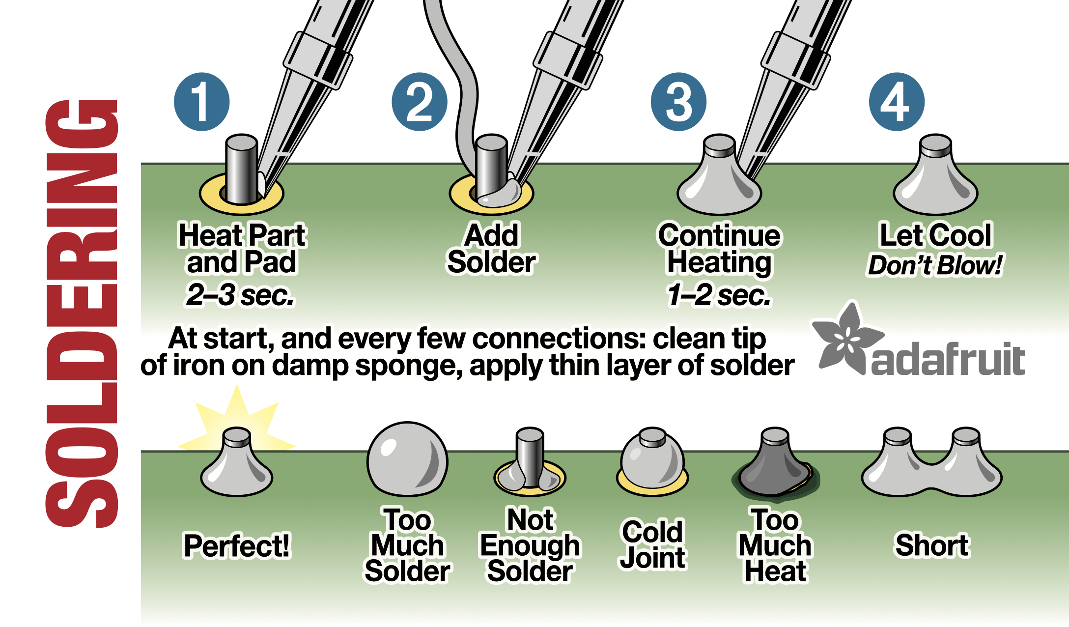
Here’s how to do it correctly:

• Use thin solder wire for electronics, with flux core.

• Heat up a soldering iron, with a fine but no too fine tip, enough that the soldering process itself is done within a few seconds.

• Get a “third hand”-tool (see below) to hold connector and cable exactly in position.
The free end of the not pre-tinned wire fully sticks in the empty hole of the connector pin.

• Soldering tip and solder wire touch the joint almost at the same time (opposed to the picture below, I didn‘t find a better one), melting just enough solder to fill the hole.
Pull away the solder wire, and continue heating for ca. 2-3 seconds, to make sure wire and pin are heated enough to make a good tinning and joint.
This is a one-step process, no pre-tinning necessary.

• After cooling down a nice tin-surface should exist, with the tin visibly linked to wire and pin.
The excess flux creates an almost invisible skin on the metal, protecting it from environmental influence.

https://karpova-lab.github.io/cerebro/_images/soldering101.png


• BTW: to remove the lacquer isolation on e.g. headphones cables, heat, not burn it away with a gas lighter.
Alternatively the soldering iron at 380 °C melts it away while (only in this case) tinning the ends.


Not the best, but the classical “third hand tool”, lots of usable variants exist.
I even have a board made with the most common connector’s conterparts mounted, to stick the connector to be soldered into.
On this one I usually remove the loupe and use strong reading glasses or a working microscope instead:
https://m.media-amazon.com/images/I/51PWjXLHSvL._AC_SX679_.jpg

Re: Wiring from D-sub contact

big_smile  I meant the solder cups on the contact. My mistake. I dont own a solder pot.

I dont grease the cups up in flux paste either. The paste is nice for flat and convex. I think it provides a really nice flow to the solder even beyond the rosin core.

So for an XLR contact with solder cups : put 2-3mm solder in cup, heat, reheat, put in wire. If you have an easier method im all ears smile I wouldnt come here for a basic soldering lesson, soldering those thick plated contacts just had me worried. Not a problem anymore bcs that idea is scrapped.

"Alternatively the soldering iron at 380 °C melts it away while (only in this case) tinning the ends." This is the method I use. Lost a fortune in headsets before I learned this. Im CC Sony Walkman generation you know.

ADI-2 DAC, ADI-2 PRO, DigifaceUSB, UCXII, ARC, HEGEL.h80, KEF.ls50, HD650, ie400pro _,.\''/.,_

Re: Wiring from D-sub contact

I didnt mean I have nothing to learn, but basic soldering maybe isnt for RME forum? ,but why not ppl talk about some other crazy stuff here so. smile

Im gonna put my money there my mouth is, so you trash can my project after I built it big_smile Thnx again for advice and sparring smile

ADI-2 DAC, ADI-2 PRO, DigifaceUSB, UCXII, ARC, HEGEL.h80, KEF.ls50, HD650, ie400pro _,.\''/.,_

19 (edited by KaiS 2024-10-11 10:53:30)

Re: Wiring from D-sub contact

Happy_amateur wrote:

put 2-3mm solder in cup, heat, reheat, put in wire.

This part weakens the link, as the flux vaporizes and not enough flux is left for a perfect joint - although I have to admit it mustn’t necessarily be a make-or-break difference.

Still, with the introduction of lead-free solders it’s a bit more challenging to do it nicely.


When I was searching the photo I‘ve seen a majority of misinformation on the net, specifically this wrong pre-tinning approach is proposed everywhere.
If once, like me, one has seen how manual soldering is done in the industry, you understand the process.

Fortunately this happened to me when I was 16, so I started right and still can use some stuff I built then.


The key indeed is the third-hand-tool, which enables to do the soldering process in one step, like described above.

For reuse of plugs etc. I have an electrical vacuum-desolder-station.
This way I can remove all solder except for a thin coating before doing a new joint.

For XLRs with their large cups to fill I have thicker solder wire and a wider solder tip - horses for courses.

20 (edited by Happy_amateur 2024-10-12 06:42:16)

Re: Wiring from D-sub contact

"put 2-3mm solder in cup, heat, reheat, put in wire." In this description I have pre tinned the wire. Beacuse its easier to handle than loose copper threads. Thats about right smile

What you are saying is all the re/heating evaporates the (protective)flux and the quicker, and with lesser steps I do this is the better?

The protective flux? I actually thought the opposite, that the flux was destructive to the joint and washed the joints with isopropyl. You are talking about the rosin core here. And the advice is to do nothing after solder has cooled. Seems I do need some basic soldering lesson. I did study those RolO charts, but this information has evaded me. Alot of metals form their own protective oxide layer, like titanium which is actually very reactive to oxygen.

I have the third hand, and tons of vices and clamps. With mostly one offs that I do positioning can be, well. This part is directly tied to the result. I worked a lot of production in my youth, so if I would do like 10 chassi XLR a day or whatever really. I would have made fixed jigs for speed and convenience. I have learned to put some effort here. Nice to hear you got off on a good start, I can honestly say I did soldering in the past that didnt last 24 hours. I did some simple LED circiuts for plastic models. That soldering was pesky stuff. Now I have a relly nice Weller station, digital temperature is good to have.

Another question: The BO adapter that came with the UCXII(I belive). It has a ferrite bead. Do you know of recomended target frequenzy and resistance for this. And is placement of the bead important, like must it be placed closed to output from ADI2pro. I ask because I have found a series of ferrite meant to be screwed to the chassi, but this solution will put the ring roughly on the middle of cable. If this is no good I will order standard clamp on bead.

ADI-2 DAC, ADI-2 PRO, DigifaceUSB, UCXII, ARC, HEGEL.h80, KEF.ls50, HD650, ie400pro _,.\''/.,_

21 (edited by KaiS 2024-10-12 09:27:08)

Re: Wiring from D-sub contact

Tin-based solder tends to crystallize and oxidize in the long run, visible on older joints.
Known effects like tin-pest and (German) zinnfrass (tin-corrosion?) may have influence on this too.

How much and how fast depends on environmental circumstances.
Typically it takes years to decades.

Rosin protects the surface from oxygen, humidity and other adverses.
Correctly made joints look glossy silver even after decades, unprotected ones become gray and get a corny structure.
I’ve even seen some literally falling apart.


The ferrite bead is for compliance with FCC rules which manufactures have to obey, it blocks radio frequencies spread from the cable working as antenna.
The ferrite bead blocks common mode signals (signal on inner conductor and shield in-phase) of frequencies 100 MHz and above, way out of the audio range.

Practically, and for private use it can be left away.
There’s no radio interference to be expected in either direction, in or out, as ADI-2 has internal filters too.

The break-out cables that had been supplied here in Germany partly don’t have ferrite beads, and our regulations ever since are quite strong too.

If you want to add one, place it within 5 cm from ADI-2 for best effectivity.

22 (edited by Happy_amateur 2024-10-12 14:01:54)

Re: Wiring from D-sub contact

I think I see. I have a box of rosin flux. Rosin as in natural product colofonium. I knew this was in standard solder wire and meant to give flow. ,but this stuff has protective/anti-corrosive properties you say. I have heared of tin-pest before, but only for antique tin smith stuff. It makes sense, tin is tin.

The other stuff I have is synthetic paste flux, but these came with directions to clean even though they where labeled as noclean, I remember that confused me a bit. They were meant for SMD´s. There where others to even more corrosive.

You can always learn alot by yourself, but whitout schools, courses and mentoring. You are bound to miss things i guess.

Ill put those rf-beads on ice. Im gonna have E14 tubeform led bulbs close to audio electronics. If that becomes a problem I wil take it from there. No use seeing ghosts in broad daylight.

ADI-2 DAC, ADI-2 PRO, DigifaceUSB, UCXII, ARC, HEGEL.h80, KEF.ls50, HD650, ie400pro _,.\''/.,_

Re: Wiring from D-sub contact

SMD soldering is completely different.

The part usually is placed on the board with little drops of solder paste underneath, on the contact areas.
The paste contains flux and solder metal powder, typically with low melting point down to 170 °C.
Then whole boards are heated in an oven, or for single parts replacement with an air-heatgun.

If one is very experienced it‘s possible to work on SMD board repairs with an fine-tipped soldering iron, a method I sometimes prefer, as I can aim more precisely on the single part than with a heatgun.

The SMD solder flux has to be removed with proper solvents.
I do use a mix of isopropyl alcohol and distilled water about 50:50% (exact ration doesn’t matter).
The fluid is sucked away with a vacuum hose.

Re: Wiring from D-sub contact

KaiS wrote:

SMD soldering is completely different.

The part usually is placed on the board with little drops of solder paste underneath, on the contact areas.
The paste contains flux and solder metal powder, typically with low melting point down to 170 °C.
Then whole boards are heated in an oven, or for single parts replacement with an air-heatgun.

If one is very experienced it‘s possible to work on SMD board repairs with an fine-tipped soldering iron, a method I sometimes prefer, as I can aim more precisely on the single part than with a heatgun.

The SMD solder flux has to be removed with proper solvents.
I do use a mix of isopropyl alcohol and distilled water about 50:50% (exact ration doesn’t matter).
The fluid is sucked away with a vacuum hose.

Now your making me look foolish big_smile Its not that bad. This is just another paste recomended for some solder I bought. Its not the metal-packed kind. Its also at the lower end of those corrosive, acidic or whatever they put in there. Basicly synthetic rosin. Its meant for SMD and other board work. Its creators maybe didnt have audio adapters in mind. Just like that smile

The other rosin I have, the colofonium kind. It works good, but its also really gluey and nasty stuff. The synthetic is much swifter and cleaner to use.
The pentaconn I mentioned. Solder area are rings inside the contact. I used a small amount of extra flux and soldered from underside to get some gravitational help, instead of letting solder flow over the ring from top. Wires were alternated from left and right. I feel I couldnt have done this operation whitout the extra flux. Its just not enough in the rosin core of wire, and some of my solders dont have flux-core at all. Low-temp solder also really helped. The process was also very quick, no messing around.

About the coaxial adapters, I just need to adjust ambition from time to time. I thank you for that!

ADI-2 DAC, ADI-2 PRO, DigifaceUSB, UCXII, ARC, HEGEL.h80, KEF.ls50, HD650, ie400pro _,.\''/.,_

Re: Wiring from D-sub contact

While I have you here its another problem I would like a reflection to, like a thought experiment:

You build a BO-box with a patchfield at the back. Now you want duplicates at the front. Just wired point to point from the back contacts.

What would happen electrically if:

You use two wired output contacts at the same time.

Feed two different digital signals into the same input

short-circuit front to back with a cable

ADI-2 DAC, ADI-2 PRO, DigifaceUSB, UCXII, ARC, HEGEL.h80, KEF.ls50, HD650, ie400pro _,.\''/.,_

26 (edited by KaiS 2024-10-13 16:04:01)

Re: Wiring from D-sub contact

The wiring should:

Go like a daisy chain:
ADI-2——OUT2——OUT1.

NOT like a Y-split:
ADI-2——OUT2
        |___
OUT1.

The red line cable needs needs to be as short as ever possibly, few cm only.

If only one out is used, it should preferably be OUT1, the one at the end of the Daisy-chain, as this is 100% correct termination.


For AES, although impedance termination is incorrect , feeding two or more destinations from one source does work if relatively short cables are used.

For SPDIF usually it doesn’t work, the electrical signal level mostly gets too low when feeding two destinations from one source.

Re: Wiring from D-sub contact

Very interesting! Im also curios about the ADI2profsrbe. Can input take a double signal or even a shortcircuit, or will it toast something. Would this setup be idiot-proof connected to the ADI2PRO?

ADI-2 DAC, ADI-2 PRO, DigifaceUSB, UCXII, ARC, HEGEL.h80, KEF.ls50, HD650, ie400pro _,.\''/.,_

28 (edited by KaiS 2024-10-13 18:45:28)

Re: Wiring from D-sub contact

Idiot-proof does not exist, the idiots are too inventive smile
But - no toasting ahead, the outputs are short-circuit-proof.


If you really need distribution of digital signals, an active digital matrix switch-box would be a good idea.

Re: Wiring from D-sub contact

big_smile Thats so true.

Reccon RME made this as good as it could be. So no toasting.

That sounds expensive, but i will check out

ADI-2 DAC, ADI-2 PRO, DigifaceUSB, UCXII, ARC, HEGEL.h80, KEF.ls50, HD650, ie400pro _,.\''/.,_

Re: Wiring from D-sub contact

I checked those switch boxes. Nice, but kinda over the top for me smile

Theres another thing I wanted to ask: Im looking for Microcandela and nanometer rating for ADI2profsrbe amber diodes. Or a part number? I need some effect lightning to match, and wanted to try myself for some simple circuitry. Im gonna have pinned diodes, but want them as close as possible

ADI-2 DAC, ADI-2 PRO, DigifaceUSB, UCXII, ARC, HEGEL.h80, KEF.ls50, HD650, ie400pro _,.\''/.,_